Flange Face Surface Finish
With flange Face the form and implementation of the side of a flens are meant, where a sealing ring or gasket will be placed.

Different types of flange faces are used as the contact surfaces to seat the sealing gasket material. ASME B16.5 and B16.47 define various types of flange facings, including the raised face, the large male and female facings which have identical dimensions to provide a relatively large contact area.
The ASME B16.5 code requires that the flange face (raised face and flat face) has a specific roughness to ensure that this surface be compatible with the gasket and provide a high quality seal.
A serrated finish, either concentric or spiral, is required with 30 to 55 grooves per inch and a resultant roughness between 125 and 500 micro inches. This allows for various grades of surface finish to be made available by flange manufactures for the gasket contact surface of metal flanges.
The picture shows a serrated finish on a Raised Face.
The most used types are:
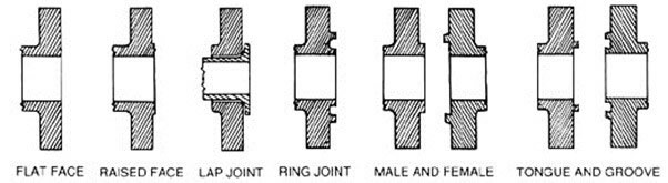

- Raised Face (RF)
- Flat Face (FF)
- Ring-Type Joint (RTJ)
- male-and-female (M&F)
- tongue-and-groove (T&G)
- Groove to Flat
- Question
- The most used Surfaces
Other flange facings covered by these standards include the large and small tongue-and-groove facings, and the ring joint facing specifically for ring joint type metal gaskets.
Raised Face (RF)
Raised FaceThe Raised Face flange is the most common type used in process plant applications, and is easily to identify. It is referred to as a raised face because the gasket surfaces are raised above the bolting circle face. This face type allows the use of a wide combination of gasket designs, including flat ring sheet types and metallic composites such as spiral wound and double jacketed types. The purpose of a RF flange is to concentrate more pressure on a smaller gasket area and thereby increase the pressure containment capability of the joint. Diameter and height are in ASME B16.5 defined, by pressure class and diameter. Pressure rating of the flange determines the height of the raised face.
The typical flange face finish for ASME B16.5 RF flanges is 125 to 250 µin Ra (3 to 6 µm Ra).

For the height measures H and B of all described dimensions of flanges on this website, with exception of the Lap Joint flange, it is important to understand and remember the following:
In pressure classes 150 and 300, the height of raised face is approximately 1.6 mm (1/16 inch). In these two pressure classes, almost all suppliers of flanges, show in their catalog or brochure, the H and B dimensions including the raised face height. (Fig. 1)
In pressure classes 400, 600, 900, 1500 & 2500, the height of raised face is approximately 6.4 mm (1/4 inch). In these pressure classes, most suppliers show the H and B dimensions excluding the raised face height. (Fig. 2)
Flat Face (FF)

The Flat Face flange has a gasket surface in the same plane as the bolting circle face. Applications using flat face flanges are frequently those in which the mating flange or flanged fitting is made from a casting.
Flat face flanges are never to be bolted to a raised face flange. ASME B31.1 says that when connecting flat face cast iron flanges to carbon steel flanges, the raised face on the carbon steel flange must be removed, and that a full face gasket is required.
This is to keep the thin, bittle cast iron flange from being sprung into the gap caused by the raised face of the carbon steel flange.
Ring-Type Joint (RTJ)
The Ring Type Joint flanges are typically used in high pressure (Class 600 and higher rating) and/or high temperature services above 800°F (427°C). They have grooves cut into their faces which steel ring gaskets. The flanges seal when tightened bolts compress the gasket between the flanges into the grooves, deforming (or Coining) the gasket to make intimate contact inside the grooves, creating a metal to metal seal.
An RTJ flange may have a raised face with a ring groove machined into it. This raised face does not serve as any part of the sealing means. For RTJ flanges that seal with ring gaskets, the raised faces of the connected and tightened flanges may contact each other. In this case the compressed gasket will not bear additional load beyond the bolt tension, vibration and movement cannot further crush the gasket and lessen the connecting tension.
Ring Type Joint gaskets are metallic sealing rings, suitable for high-pressure and high-temperature applications. They are always applied to special, accompanying flanges which ensure good, reliable sealing with the correct choice of profiles and material.
Ring Type Joint gaskets are designed to seal by "initial line contact" or wedging action between the mating flange and the gasket. By applying pressure on the seal interface through bolt force, the "softer" metal of the gasket flows into the microfine structure of the harder flange material, and creating a very tight and efficient seal.
The most applied rings are:
1. Type R-Oval according to ASME B16.20
The original style of metallic ring joint. Used on round bottomed groove flanges though can also be used on later, flat-bottomed groove flanges. Suitable for ASME B16.5 flanges from Class 150 to 2500.
2. Type R-Octagonal according to ASME B16.20
An improved design over the original Oval design. However these can be used only in flat-bottomed groove flanges. Suitable for ASME B16.5 flanges from Class 150 to 2500.
The octagonal cross section has a higher sealing efficiency than the oval and would be the preferred gasket. However, only the oval cross section can be used in the old type round bottom groove. The newer flat bottom groove design will accept either the oval or the octagonal cross section.
The sealing surfaces on the ring joint grooves must be smoothly finished to 63 Microinches and be free of objectionable ridges, tool or chatter marks. They seal by an initial line contact or a wedging action as the compressive forces are applied. The hardness of the ring should always be less than the hardness of the flanges.
Style R ring type joints are designed to seal pressure up to 6,250 psi in accordance with ASME B16.5 pressure ratings and up to 5,000 psi.
male-and-female (M&F)

With this type the flanges also must be matched. One flange face has an area that extends beyond the normal flange face (Male). The other flange or mating flange has a matching depression (Female) machined into it's face.
The female face is 3/16-inch deep, the male face is1/4-inch high, and both are smooth finished. The outer diameter of the female face acts to locate and retain the gasket. Custom male and female facings are commonly found on the Heat Exchanger shell to channel and cover flanges.
Depth of female (recessed) face normally equal to or less than height of male (raised) face, to prevent metal-to-metal contact during gasket compression
Recessed O.D. normally is not more than 1/16″ larger than the O.D. of the male face
Joint must be pried apart for disassembly
tongue-and-groove (T&G)

The Tongue and Groove faces of this flanges must be matched. One flange face has a raised ring (Tongue) machined onto the flange face while the mating flange has a matching depression (Groove) machined into it’s face.
tongue-and-groove facings are standardized in both large and small types. They differ from male-and-female in that the inside diameters of the tongue-and-groove do not extend into the flange base, thus retaining the gasket on its inner and outer diameter. These are commonly found on pump covers and Valve Bonnets.
tongue-and-groove joints also have an advantage in that they are self-aligning and act as a reservoir for the adhesive. The scarf joint keeps the axis of loading in line with the joint and does not require a major machining operation.
General flange faces such as the RTJ, T&G and the F&M shall never be bolted together. The reason for this is that the contact surfaces do not match and there is no gasket that has one type on one side and another type on the other side.
Groove to Flat
- One flange face is flat, the other is recessed
- For applications requiring accurate control of gasket compression
- Only resilient gaskets are recommended —spiral wound, hollow metal O-ring, pressure-actuated, and metal-jacketed gaskets
Advantages and disadvantages of T&G and M&F flange faces
Advantages:
Better sealing properties, more precise location and exact compression af sealing material, utilization of other, more suitable sealing and spezialized sealing material (O-rings).
Disadvantages:
Commercial availabillity and cost. Normal raised faced is far more common and ready available both regarding Valves, flanges and sealing material. Another complexity is that some rigid rules must be applied to the piping design. Do you order Valves to be female end both sides, or on one side maybe, in which case do you point all male ends in the flow direction, or what. Same applies to any flanged joint / vessel connection of course.
What is the difference between a RTJ, FF, and RF flange on seals and thermowells?
The raised face, RF, is the standard process connection on our third party seals and thermowells. Both have options for a RTJ and FF type flange connections. The Raised Face (RF) is the most common type used in process plant applications.
The gasket surface of the flange is raised above the bolting circle face. A Ring-type Joint (RTJ) can also have a raised gasket face with the difference being the ring groove machined in this face.
This groove will accommodate a steel ring gasket for flange mating. The Flat Face, FF, flange has a gasket surface that is in the same plane as the bolting circle face.
None of these three flange types are interchangeable between types, i.e. RTJ flange cannot be mated to a RF flange.
Serration on the Flange Face
The flange face has small grooves as you can see in the image. This machining is known as a serration. Flange face can be smooth or serrated type. Which type of face to use is depends on the type of the gasket and service of the fluid.

Smooth finish is used with metallic gasket whereas serrated finish is used with non-metallic gasket. Soft material of gaskets is set in this serration and prevent liquid or gas from passing from flange joint.
Sunny Steel can be spiral or concentric rings as you can see in the slide. Concentric rings type finishing is used when fluid is of very low density. If you use spiral type finish with very low density fluid, it may find leakage path through the spiral cavity.
Serration of flange face is specified in RMS (Root Mean Square) or AARH (Arithmetic Average Rough Height), the most common value of serrated face is 120-250 AARH. Comparator gauge is used to check serration of the flange. In the image, you can see the how gauge is used to verify the value of serration.
The most used Surfaces
A serrated finish, either concentric or spiral, is required with 30 to 55 grooves per inch and a resultant roughness between 125 and 500 microinches.

This allows for various grades of surface finish to be made available by flange manufactures for the gasket contact surface of metal flanges. These grades are often referred to by name e.g. stock finish. The exact definition of each grade may differ between manufacturers, but can be generalised as follows;

Stock Finish
The gasket contact surface is typically formed by a continuous (sometimes called phonographic) spiral groove generated by a 1.6mm radius round-nosed tool at a feed rate of 0.8mm per revolution with a depth of 0.15mm. This will result in a roughness between Ra 3.2 and 12.5 micrometers (125 - 500 microinch).
Smooth Finish
No definite tool marking should be apparent to the naked eye. This is typically achieved by having the gasket contact surface formed by a continuous (sometimes called phonographic) spiral groove generated by a 0.8mm radius round-nosed tool at a feed rate of 0.3mm per revolution with a depth of 0.05mm. This will result in a roughness between Ra 3.2 and 6.3 micrometers (125 - 250 microinch).
Hydrogen Service Finish
The finish for flanges in hydrogen service is very smooth, typically between Ra 2 and 3.2 micrometers (79 - 125 microinch).
Cold Water Finish
The flange face appears as mirror like. This flange finish is usually expected to be used with metal to metal contact, i.e. without a gasket. It is seldom used in the oil, petrochem and related industries.
Measuring Surface Roughness
Flange finish is generally measured by visual and tactile means. Comparing the feel of the machined face with that of a surface finish comparator gauge, occasionally referred to as a Rupert gauge, is considered adequate.
There are two common methods of expressing roughness. They are the Arithmetic Average Roughness Height (AARH) and the Root Mean Square (RMS) Average.
Arithmetic Average Roughness Height- Calculation of the Arithmetic Average Roughness Height involves measuring the distance of the peaks and valleys and performing an arithmetic average of the measurements.
Root Mean Square Average - Calculation of the Root Mean Square Average involves measuring the distance of peaks and valleys, adding the square of these measurements and calculating the square root of the total.
The RMS value is approximately 11% higher than the AARH value.


