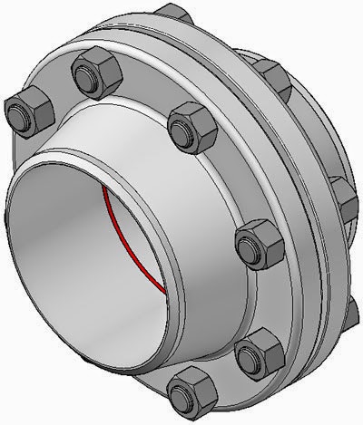
Flanges General
A flange is a method of connecting pipes, valves, pumps and other equipment to form a piping system. It also provides easy access for cleaning, inspection or modification. Flanges are usually welded or screwed. Flanged joints are made by bolting together two flanges with a gasket between them to provide a seal.
Types of Flanges
The most used flange types in Petro and chemical industry are:
All types except the Lap Joint flange are provided with a raised flange face.
|
Special Flanges
Except the most used standard flanges, there are still a number of special flanges such as:
|
Materials for Flanges
Pipe flanges are manufactured in all the different materials like stainless steel, cast iron, aluminium, brass, bronze, plastic etc. but the most used material is forged carbon steel and have machined surfaces.
In addition, flanges, like fittings and pipes, for specific purposes sometimes internally equipped with layers of materials of a completely different quality as the flanges themselves, which are "lined flanges".
The material of a flange, is basically set during the choice of the pipe, in most cases, a flange is of the same material as the pipe.
All flanges, discussed on this website fall under the ASME en ASTM standards, unless otherwise indicated. ASME B16.5 describes dimensions, dimensional tolerances etc. and ASTM the different material qualities.
Dimensions of Flanges
Each flange according to ASME B16.5 has a number of standard dimensions. If a draftsman in Japan or a work preparer in Canada or a pipefitter in Australia is speaking about a Welding Neck flange NPS 6, Class 150, Schedule 40 ASME B16.5, then it goes over the flange which in the image here below is shown.
If the flange is ordered, the supplier want to know the material quality. For example ASTM A105 is a forged carbon steel flange, while A182 is a forged stainless steel flange.
So, in a correct order to a supplier two standards must be specified:
Welding Neck flange NPS 6, Class 150, Schedule 40, ASME B16.5 / ASTM A105.

The flange above has 8 bolt holes, and a welding bevel of 37.5 degrees (red circle). All given dimensions are in millimeters. The raised face (RF) does not need to be specified, because according to ASME B16.5, each flange is standard delivered with a raised face. Only a different design (Ring Type Joint (RTJ), Flat Face (FF) etc.), should be specified.
Bolted Flange connections
A bolted flange connection is a complex combination of many factors (Flange, Bolts, Process, Temperature, Pressure, Medium). All these various elements are interrelated and depend upon one another to achieve a successful result.
The reliability of the flanged joint depends critically upon competent control of the joint making process.
The reliability of the flanged joint depends critically upon competent control of the joint making process.
 |
| Typical bolted flange connection |
Quoting from John H. Bickford's book, "An Introduction to the Design and Behavior of Bolted Joints":
That all important clamping force which holds the joint together - and without which there would be no joint - is not created by a good joint designer, nor by high quality parts. It is created by the mechanic on the job site, using the tools, procedures, and working conditions we have provided him with... And further: The final, essential creator of the force is the mechanic, and the time of creation is during assembly. So it's very important for us to understand this process.
The industry has recognized the critical nature of installation and assembly for several years.
In Europe, the emphasis has been on ensuring that joint making is undertaken by trained and validated technicians and this has led to the publication of a European Technical standard: TS EN 1591 Part 4 entitled "Flanges and their joints. Design rules for gasketed circular flange connections. Qualification of personnel competency in the assembly of bolted joints fitted to equipment subject to the Pressure Equipment Directive (PED)".
In Europe, the emphasis has been on ensuring that joint making is undertaken by trained and validated technicians and this has led to the publication of a European Technical standard: TS EN 1591 Part 4 entitled "Flanges and their joints. Design rules for gasketed circular flange connections. Qualification of personnel competency in the assembly of bolted joints fitted to equipment subject to the Pressure Equipment Directive (PED)".
The standard provides a methodology for the training and assessment of technicians involved in the making and breaking of flange joints and can be viewed as being analogous to the training required for welders involved with pressure vessel work. Its publication demonstrates the importance placed upon the competent control of joint making process in ensuring leak-free performance from the flange.
The gasket is but one of many reasons a bolted flange joint connection can leak.
Even when all the complex inter-related components of a bolted joint flange connection work in perfect harmony, the single most important factor leading to success or failure of that bolted flange connection will be attention given to properinstallation and assembly procedures by the person installing the gasket. If done properly, the assembly will remain leak-free for the target life expectancy.
Even when all the complex inter-related components of a bolted joint flange connection work in perfect harmony, the single most important factor leading to success or failure of that bolted flange connection will be attention given to properinstallation and assembly procedures by the person installing the gasket. If done properly, the assembly will remain leak-free for the target life expectancy.
